Typical connection diagram of the LV 25-P voltage sensor.

By A Mystery Man Writer
Typical connection diagram of the LV 25-P voltage sensor.

Step-by-step design of a voltage sensing PCB — Switchcraft

Typical connection diagram of the LV 25-P voltage sensor.

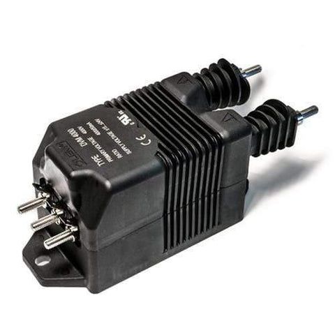
LV 25-P, C/L Voltage Transducer, 400V, 25mA Output

Typical connection diagram of the LV 25-P voltage sensor.

Typical connection diagram of the LV 25-P voltage sensor

Typical connection diagram of the LV 25-P voltage sensor.

Schematic diagram for LV 25-P voltage transducer.

Typical connection diagram of the LV 25-P voltage sensor.

3: The LEM LV 25-P voltage transducer schematic.

Typical connection diagram of the LV 25-P voltage sensor.

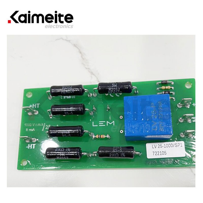
LV25-P LV25-P voltage sensor - Kaimeite

Typical connection diagram of the LV 25-P voltage sensor.

Internal circuit diagram of LEM LV25P voltage transducer

Typical connection diagram of the LV 25-P voltage sensor.

electronic too free: Isolated AC voltage sensing using LV25-P

Typical connection diagram of the LV 25-P voltage sensor.

Design and Validation of a Modular Control Platform for a Voltage

Typical connection diagram of the LV 25-P voltage sensor.

Design and Validation of a Modular Control Platform for a Voltage

Typical connection diagram of the LV 25-P voltage sensor.

Interfacing 0-25V DC Voltage Sensor with Arduino